Project Log: One-day Stereo Cabinet
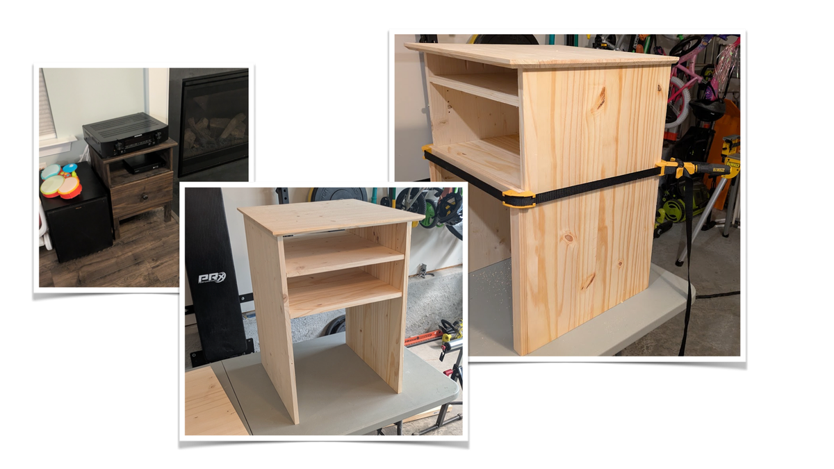
Having recently wrapped up a long-running woodworking project to build a linen chest for the kids' room, I was looking for something new to work on that also wouldn't drag out for months the way that project had.
One idea that had been kicking around for years is a replacement for the IKEA nightstand that we had been using as a cabinet for our stereo receiver, Roku, and DVD player.
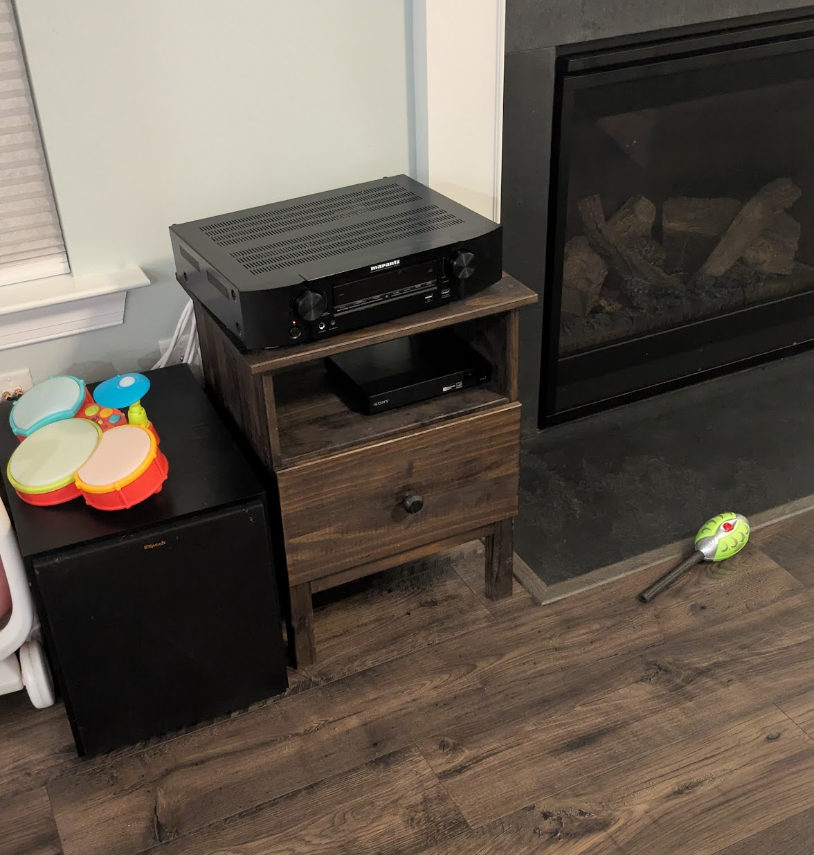
We bought it a few years ago, thinking the receiver would fit in the opening of the nightstand, which it didn't, and that we would have a use for the drawer for storage, which we haven't. The drawer has turned into a repository for kids toys, which is fine enough, but we would really like the whole setup to sit on top of the subwoofer instead of next to it.
Day Zero
I had all day Saturday to work on this, and the project seemed tractable in a day. Friday night, rather than drawing up plans on paper, I borrowed a page from my 3D printing days and put together a design in Fusion in less than an hour
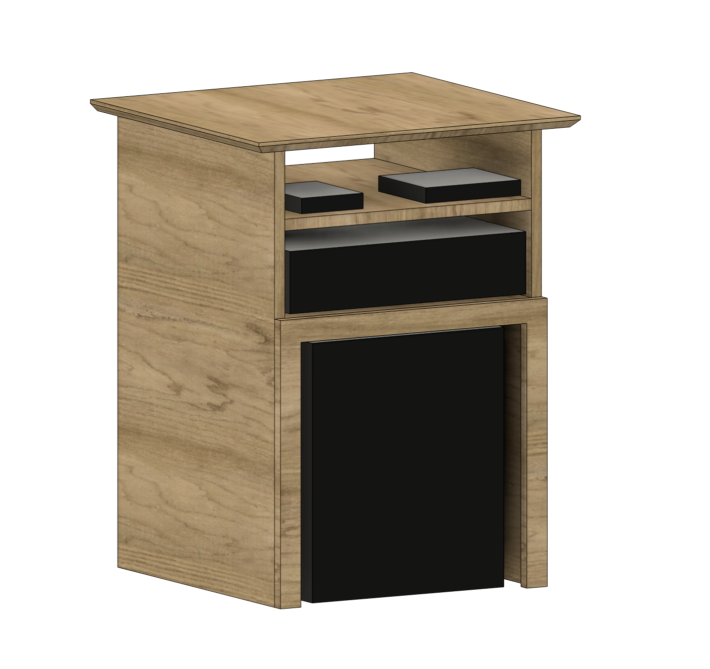
Steph gave the design the thumbs up, and went to bed with plans to hit the hardware store first thing in the morning. I had some vague ideas how I wanted to 3D print a door frame with an acrylic pane in the middle to keep the kids out of the electronics but that was still unresolved. Building the wood cabinet was the main goal.
Day One
By the end of the first day of the one-day project, it was... about 75% done. {Yes, I did take Hofstadter's Law into account.}
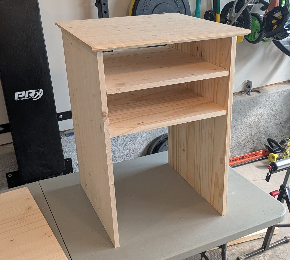
The main difficulty on the first day was getting the four main pieces square: the top, the two sides, and the fixed bottom shelf. I very much underestimated how precise I needed to be when attaching those. Also, using pocket hole screws to attach these four pieces turned out to be very unforgiving, because you can't just move a pocket hole screw by a quarter of an inch. It just goes right back to the hole you already made when assembling the first time. Of the pocket hole screws I drilled on this first day, more than half had to be re-drilled just so could have a do-over in squaring everything up before assembly.
If I had it to do over again, I would probably just cut some 1"x1" corner blocks and screw those into the sides, then use separate screws to affix the top and shelf. That would have greatly simplified the process of getting the shelf flat and square, because holding it up, holding it square, and driving the screws was a three-handed operation. In the end, I cut four identical 1x2 spacers, turned the whole thing so it was sitting on the top, rested the shelf on the spacers so by definition it was square to the top at the four corners, and screwed it in that way.
Cutting Chamfers
I knew the time constraints on the project meant I did not have a lot of time for embellishments but one thing I wanted to do both for aesthetics and for function was to put a chamfer on the underside of the top of the cabinet. I have an electric trim router that can do this just fine, but I also knew that this was a job that a craftsman with a hand plane 100 years ago could do by eye and feel.
I started cutting the chamfer by hand and realized I didn't have a good reference for what 45º was. The simplest solution was also the silliest, which was to slap my magnetic angle finder on the side of the plane and try to hold 45 on it while I planed.
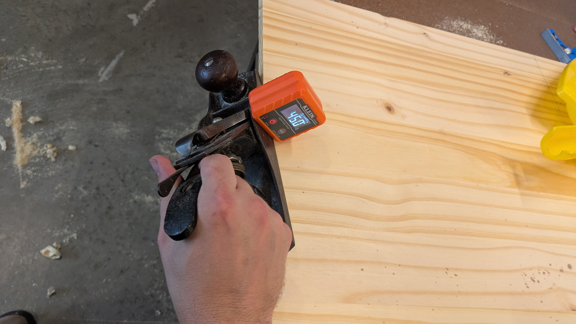
The picture looks goofy and it absolutely was. It was not particularly successful and while trying to watch the digital readout, I wasn't really paying attention to the workpiece or how I was holding the plane. Cutting one edge this way worked fine but it mostly gave me time to think about a better way to solve the problem.
After doing one edge that way, I broke out the high tech marking instrument (pencil) and adjustable orthogonal measuring apparatus (combination square) and just drew a line 3/8" from the edge on both faces I was trying to cut. I then shaded in all the area I wanted to remove. This made it very easy to see visually if one pencil area was bigger than the other, which meant I was taking off more material on one face than the other. Working through it that way gave much better results.
Breakthrough About The Door
By dinner time, the structure had been assembled as squarely as I could manage, and I had cut the middle shelf as well as the peg holes to make it height-adjustable.
After the kids were in bed, I cut the pieces for the facade and went to dry-fit them. At that point, I realized that I didn't want to 3D-print the frame for the door. The door should be made of the same wood as the facade. Obvious in retrospect, I know.
I took the remaining facade material and cut enough for a frame that would cover the upper half of the cabinet where all the electronics would go. To build it, I used a traditional cabinet-door-style stiles-and-rails construction. The long pieces got a 1/4" groove cut with the Stanley 45 Combination Plane which went pleasantly quickly.
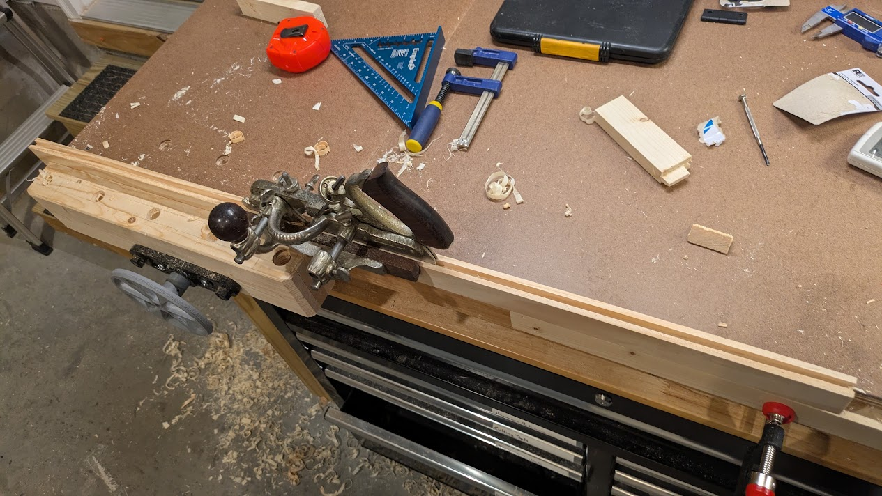
The short, side pieces got a 1/8" groove cut in them, 3mm wide to hold the 2mm sheet of acrylic. The short pieces then also had the 1/4" tenon cheeks cut on each side, also with the Stanley 45 which went surprisingly easily given it was cutting cross grain. It's not the prettiest, and I'm sure with more test cuts I could have gotten it looking nicer, but the time crunch was on so I just went with what I had.
The main concern at the end of day one was the amount of wobble and racking on the unit. I knew before I started that it would be an issue to deal with, and had bought some metal L brackets to put on the back of the unit to stiffen it, but I was unsure if they would be enough. {In the end, with the facade assembled, it was stiff enough that I chose to leave the brackets off.}
Day Two
Cleaning up at the end of the day, I realized that the front facade below the door should not be three separate pieces of wood, but should be joined with half-lap joints at the corners.
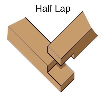

This classic joint is surprisingly strong despite the simple geometry. This would make the individual pieces resist the racking force quite strongly, and meant I would need fewer screws to attach them from the back since, once assembled, they would act as a single piece.
Unfortunately, I was just shy on material to remake those pieces long enough to be half-lapped. A quick jaunt to the hardware store and back was not that much time lost and brought a smile to my face.
Cutting The Half Laps
This part took way longer than planned. In the past few months I have dabbled with a few different ways to cut half laps. The router table generally produces highly accurate, flat bottomed half-laps, but at the cost of tear-out. As the spinning router bit comes out the trailing face of the workpiece, it tends to splinter and tear the wood fibers out instead of cleanly cutting them. The fix to this is simple but somewhat annoying: have another piece of scrap backing your workpiece as a sacrificial support. It gets chewed up by the router bit, but it gives the wood fibers on the trailing edge of the workpiece no place to go and thus gives you a nice clean cut.
However, I had also experimented with cutting half laps on the table saw and had found it generally workable if a bit slow and tedious. Rather than the wide cutter of the router, you have to nibble away, one saw blade width at a time at the half-lap. I only had four of them to cut, and the table saw was set up anyway, so I thought I would dial in the right depth of cut and be on my way.
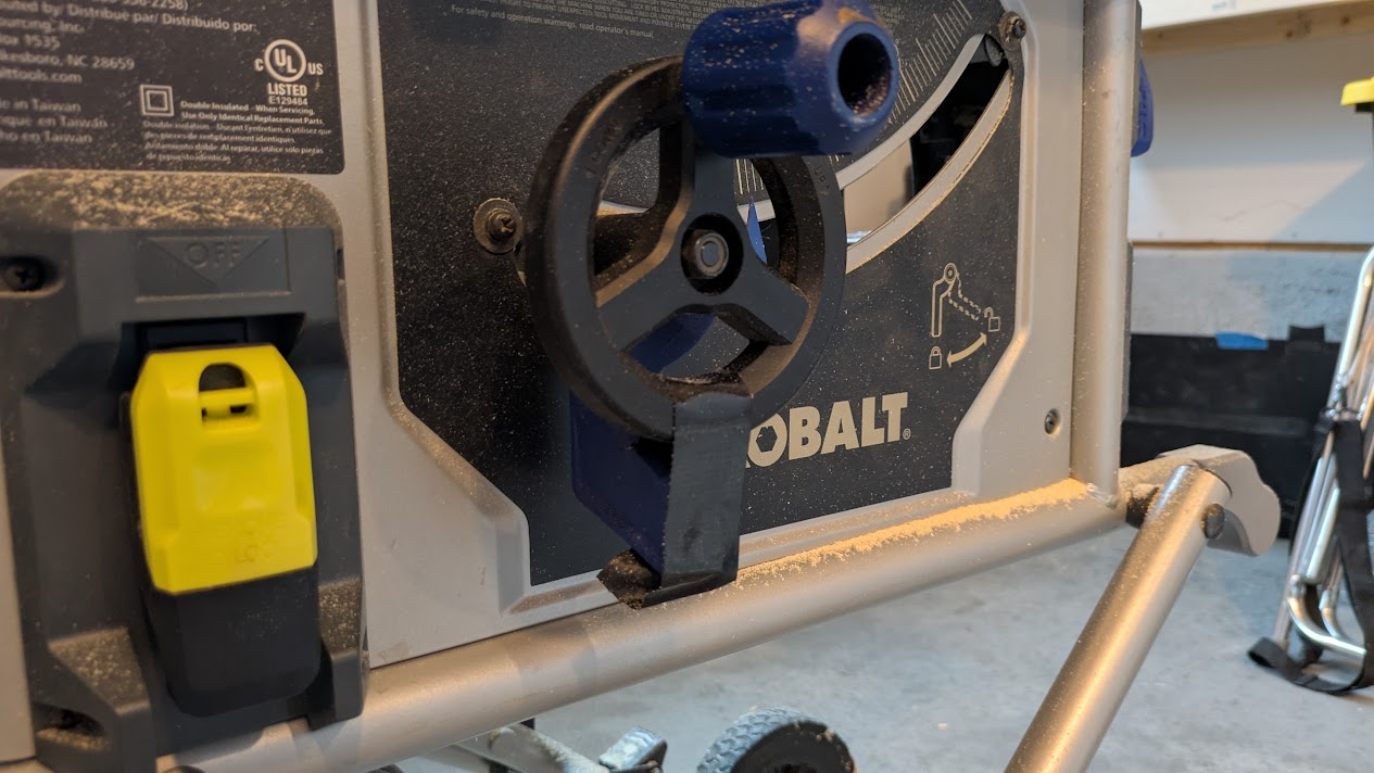
Unfortunately, it was not to be. I found this out by doing test cuts on scrap pieces before cutting my workpieces. Over and over again I would adjust the blade height and over and over again it would be too high or to low. I was shooting for 3/8" (.375"), exactly half the width of the select pine 1x2s I was using. But over and over again I either got .350" or .400" and I could not figure out why. I kept trying until I noticed the wheel adjuster for the blade height was not in the same place before and after a cut. I would set the blade to .375", turn on the saw, and the vibration would cause it to sink down to .350". This is a budget contractor saw so I can't really complain too much, and once the problem was identified the fix was obvious:
Putting On The Hinges
After a dinner break to let the glue on the half laps and door frame set up, it was time to attach the door to the frame. I had bought generic, cheap hinges at the home center, thinking I didn't need any fancy strength or soft-close hardware.
I got the hinges mounted simply enough and they swung open easily and freely, but just wouldn't... quite... close. I could feel the wood bending and springing open when I let off pressure. I'm sure I could have 3D-printed a strong enough latch to hold the door closed, but I knew something wasn't right, and forcing the door closed would warp the wood over time.
I tried a few things and nothing worked, until a shot in the dark at Google Gemini pointed me at the right direction: the screw heads themselves were not sitting flush with the face of the hinge, and so they were interfering with each other right at the point the hinge needed to close. Indeed, the screws that came with the hinges had tapered screw heads, but the holes were they were supposed to sit were not tapered at all. A few seconds each with a countersink bit (which made the hinges too hot to hold for a minute) let the screw heads sit flush with the top of the hinge leaf, and once reinstalled the door swung closed nicely.
Crossing The Finish Line
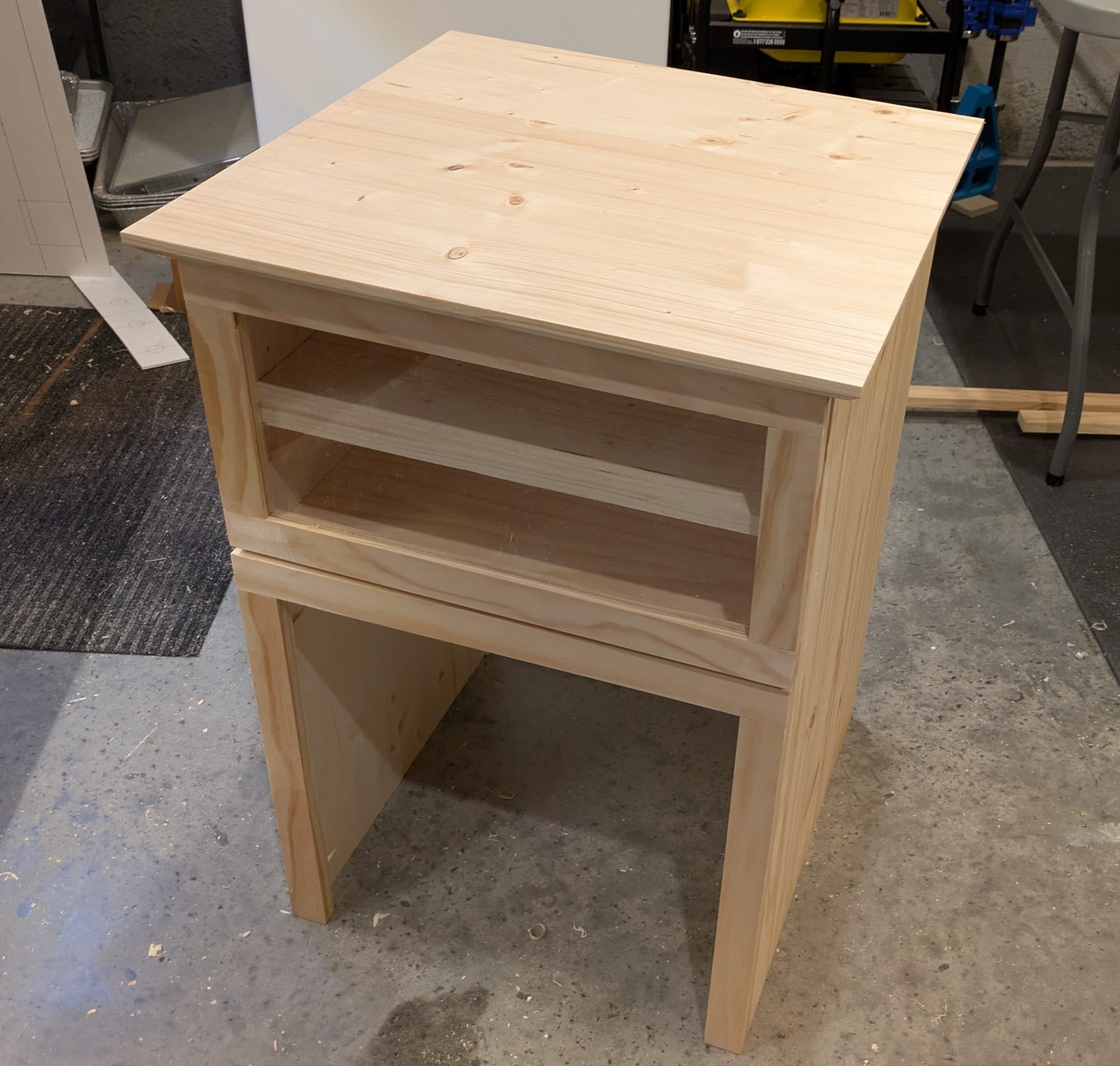
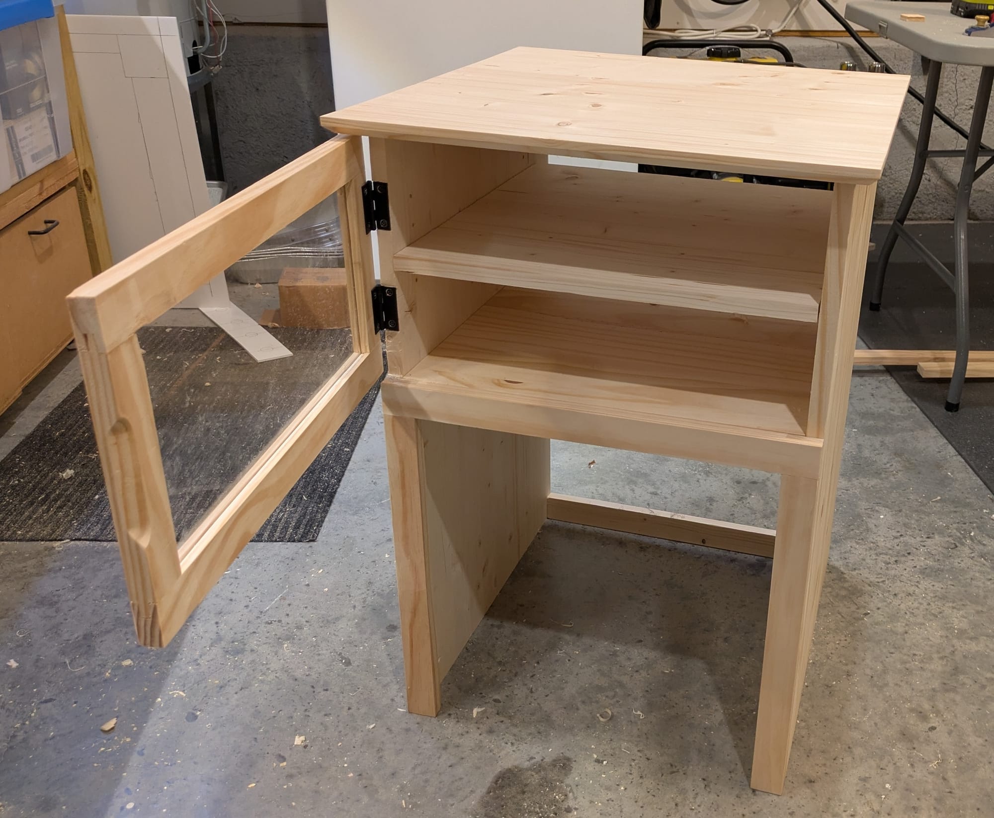
Going from design to construction complete in 48 hours definitely felt like a sprint. It still needs to be stained and finished, but by its nature that kind of work is better done in short sessions over multiple days, unlike the actual woodworking of construction.
The piece has flaws and blemishes that are the testimony of lessons learned. Having a strict time constraint was oddly freeing. It let me give up a bit of perfectionism and accept good enough. This is vernacular furniture that is ultimately meant to be functional and pleasing to the eye but not necessarily stand up to close scrutiny. And in that respect I think it succeeds.
I'm also realistic that this is a highly specialized piece of furniture: bespoke to this exact subwoofer and receiver. This is not really something our children might use and love one day. If we move and leave behind this stereo system, this cabinet would say with it it. It might as well be built-in to the house, as relatively permanent as the wired-in surround sound speakers are. But for that use, hopefully it will give us may years of simple, functional beauty.